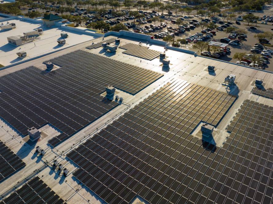
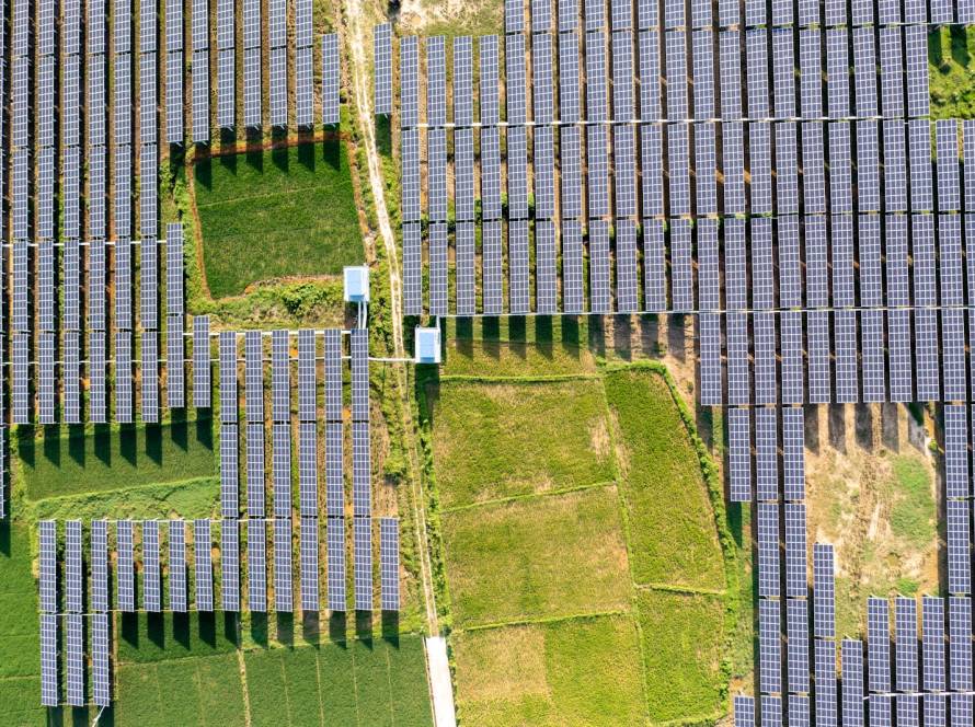
Commercial solar is a long-term investment in a facility’s energy infrastructure. Understanding why engineering matters in commercial solar projects begins with recognising that panels, inverters and batteries cannot be selected independently of the building, electrical supply, operating schedule and future energy requirements.
Engineering replaces assumptions with measured information, technical calculations and documented decisions. It gives business owners a clearer understanding of what the proposed system can achieve, which limitations must be managed and how the installation will operate safely over its service life.
Engineering Turns Energy Goals Into a Practical Design
Businesses typically consider solar to lower electricity costs, reduce peak demand, improve energy continuity or support future expansion. Engineers convert these broad objectives into a practical design by examining electricity bills, operating hours, tariff structures, maximum demand and expected changes in consumption.
This initial analysis illustrates why engineering matters in commercial solar projects, as historical consumption does not always represent future requirements. Planned machinery, additional shifts, building extensions and electric vehicle charging can all alter the facility’s load. Accounting for these changes early helps prevent premature system constraints or unnecessary oversizing.
Why Engineering Matters in Commercial Solar Projects When Analysing Loads
A monthly electricity bill reveals how much energy a facility purchased, but not exactly when that energy was used. Interval consumption data provides a more detailed picture by showing demand across different times of the day, days of the week and operating periods.
Engineers use the load profile to compare electricity consumption with expected solar generation. This helps determine how much energy can be consumed directly, how much may be exported or curtailed and whether storage could improve the result. A facility with consistent daytime demand may require a different solution from one with irregular or evening-heavy consumption.
- Daytime base load: A facility’s base load represents the electricity it uses consistently while operating. Matching solar generation to this dependable demand can increase direct consumption and reduce the amount of surplus energy requiring export, storage or curtailment.
- Short-duration demand peaks: Machinery start-ups, heating equipment, cooling systems and production processes may cause sudden increases in demand. Engineers examine whether solar or battery power can meaningfully reduce these peaks without compromising system stability.
- Operating schedules: Offices, factories, warehouses and retail facilities use electricity at different times. Shift patterns, weekend operations and seasonal closures all influence how closely the solar generation profile matches actual consumption.
- Essential and non-essential loads: Separating critical equipment from loads that can tolerate an interruption helps engineers determine backup requirements. This information is particularly important when batteries, generators or uninterruptible power supplies form part of the project.
- Future consumption changes: New production lines, longer operating hours, building extensions and electric vehicle charging can materially alter the load profile. Including realistic growth assumptions helps ensure the system can support future operations.
Load analysis helps the engineering team avoid basing a major infrastructure decision on a single monthly total. It creates a detailed picture of the facility’s actual behaviour and reveals where solar energy is likely to deliver the greatest operational and financial value.
The findings also provide a foundation for later design decisions. Array capacity, inverter output, battery size, export controls and backup arrangements can all be traced back to measured demand and clearly defined operating requirements.
Accurate Site Assessments Prevent Costly Mistakes
A detailed site assessment examines roof condition, available ground or carport space, orientation, shading and access. It should also consider drainage, waterproofing, nearby equipment, electrical rooms, cable routes and environmental conditions such as dust, heat, wind and corrosive exposure.
These observations influence the array layout, mounting method, equipment location and installation programme. Identifying a damaged roof, restricted lifting area or long cable route before construction allows the design and budget to be adjusted in a controlled manner. Without this assessment, apparently minor site conditions can cause delays, variations and remedial work.
Structural Engineering Protects the Building
Structural engineers determine whether roofs, carports and supporting structures can safely carry panels, mounting equipment and associated loads. They examine the structure’s condition, original design, attachment points and ability to accommodate installation and maintenance activities.
Recognising why engineering matters in commercial solar projects also means considering wind pressure and uplift. A mounting system must transfer these forces safely into the supporting structure without compromising waterproofing or roof integrity. Insufficient assessment can contribute to leaks, damaged sheeting, deformation or unsafe mounting points during severe weather.
- Existing structural capacity: Engineers evaluate whether the original structure and its individual components can support the additional permanent and temporary loads introduced by the installation.
- Roof condition: Corrosion, damaged sheeting, weakened timber, deteriorated waterproofing and previous alterations may affect whether the roof is suitable for solar equipment without repairs or reinforcement.
- Wind pressure and uplift: Panels and mounting systems are exposed to forces that can pull or push against the supporting structure. Attachment methods must transfer these forces safely into the building.
- Mounting and connection points: The mounting design must correspond with the underlying structural elements rather than relying only on the visible roof covering. Correct placement reduces the risk of movement and localised damage.
- Waterproofing and drainage: Roof penetrations and mounting components must not obstruct drainage or create uncontrolled water-entry points. The structural and installation designs should protect the roof’s weatherproofing.
- Maintenance loads and access: The structure must accommodate people and equipment used during installation, inspection and maintenance. Safe access routes should be considered alongside the permanent solar loads.
Structural findings may influence how many panels can be installed and where they should be positioned. In some cases, reinforcement or roof repairs may be required before the solar installation proceeds. Identifying these requirements during design allows the business to plan the work properly.
A documented structural assessment also creates accountability. It gives the project team clear loading limitations and mounting requirements, helping installers avoid unapproved changes that could affect the building’s integrity.
Electrical Engineering Ensures Correct System Sizing
Electrical design establishes how the solar installation will connect to the facility’s existing network. Engineers assess the incoming supply, transformer capacity, phases, distribution boards, fault levels, connection points and existing protection before selecting the main system ratings.
This work guides PV capacity, inverter output, string configuration, cable sizes, breakers, fuses, isolators and surge protection. The largest array that physically fits is not automatically the most appropriate. The system must remain within electrical and connection limitations while producing useful energy that matches the facility’s demand.
- PV array capacity: The number and rating of panels should reflect available space, expected generation, facility demand and the operating limits of the rest of the system.
- Inverter capacity: Engineers select inverter output according to the array, electrical supply, connection limitations and expected operating conditions. Inverter capacity affects how much generated power can be converted and used.
- String configuration: Panels must be arranged so that string voltages and currents remain within inverter operating limits under changing temperatures and environmental conditions.
- Cable sizing: Conductors are selected according to operating current, voltage drop, installation method, temperature and fault conditions. Undersized cables can overheat and waste energy.
- Protection equipment: Breakers, fuses, isolators and surge-protection devices must be coordinated with cables and equipment so that faults are disconnected safely.
- Connection points: The intended connection point must have sufficient capacity and suitable protection. Existing distribution boards or switchgear may need modification before integration can proceed.
Correct electrical sizing supports both safety and performance. A system that is too large for the connection infrastructure may require expensive upgrades, while one that is too small may fail to deliver the expected energy benefit.
Detailed calculations also give installers an approved technical basis for their work. This reduces inconsistent on-site decisions and allows commissioning personnel to verify the completed installation against defined design values.
Why Engineering Matters in Commercial Solar Projects for Grid Connection
A commercial solar system operating in parallel with the electricity network can affect network safety and power quality, even if the business intends to consume all generation on site. Grid requirements must therefore be investigated before equipment is ordered or construction begins.
The design may need to address embedded-generation approval, export limits, metering, anti-islanding and protection settings. Requirements can vary according to the electricity distributor, supply voltage and system capacity. Early technical engagement reduces the risk of rejected applications, unexpected equipment changes or an installation that cannot operate as originally intended.
Engineering Improves System Safety
Commercial solar introduces additional sources of electricity into a facility. Solar arrays may remain energised whenever light is available, while batteries, generators and the grid can introduce further energy sources. Safe isolation must account for every possible operating condition.
Engineers design earthing, surge protection, equipment labelling, emergency shutdown arrangements and safe access. They also consider ventilation, heat dissipation, fire routes and separation from combustible materials. Proper equipment placement makes routine maintenance safer and allows authorised personnel to identify and isolate different parts of the installation quickly.
Cable Routing Influences Safety and Performance
Cable length, conductor size, operating current and temperature affect voltage drop and energy losses. This helps explain why engineering matters in commercial solar projects, particularly where arrays are far from inverters or the intended connection point.
Routes must also protect cables from ultraviolet exposure, water, sharp edges, moving equipment and mechanical damage. Appropriate containment, roof penetrations and separation between circuits support long-term reliability. Poor routing can create energy losses, water-entry points and damaged insulation while making inspection and future repairs unnecessarily difficult.
- Cable distance: Longer routes can increase voltage drop and material requirements. Engineers compare possible routes to balance efficiency, safety and installation practicality.
- Operating temperature: Cables exposed to high temperatures may carry less current safely. Heat from sunlight, roofs, equipment and enclosed containment must be considered during sizing.
- Mechanical protection: Conduits, trays and other containment protect cables from impact, abrasion, sharp edges and normal activities taking place around the facility.
- Environmental exposure: Outdoor cables and containment may face ultraviolet radiation, rain, moisture, dust or corrosion. Materials should be selected for the conditions in which they will operate.
- Roof penetrations: Any penetration must be properly planned and sealed to prevent water entry. Routes should also avoid obstructing roof drainage.
- Inspection and maintenance access: Technicians must be able to inspect, test and repair cable systems safely. Concealed or inaccessible routes can make fault-finding more difficult and expensive.
A professionally planned route reduces avoidable energy losses while protecting the conductors throughout their operating life. It also ensures that cables do not create unnecessary hazards in walkways, production areas or maintenance zones.
Clear cable schedules and route drawings help installation teams follow the approved design. Once construction is complete, accurate as-built information allows future technicians to locate circuits, identify isolation points and plan repairs without unnecessary disruption.
Protection Systems Reduce Electrical Risk
Circuit breakers, fuses, isolators and surge-protection devices are selected to disconnect faults before they cause wider equipment damage or place people at risk. Their ratings must correspond with conductor capacity, operating voltage, fault current and equipment characteristics.
Anti-islanding protection is particularly important where generation operates in parallel with the grid. It prevents the system from continuing to energise a disconnected network. Export-limitation and grid-protection settings may also need to be tested during commissioning to confirm that the completed installation behaves as designed.
Why Engineering Matters in Commercial Solar Projects With Integrated Equipment
High-quality panels, inverters and batteries will not necessarily produce a dependable system if they are incompatible. Engineers check voltages, currents, operating ranges, environmental ratings, control arrangements and communication requirements before specifying equipment.
Integration becomes more complicated when solar must operate with batteries, generators, uninterruptible power supplies and the grid. Each source requires a defined operating role. Poor coordination can cause unstable transfers, nuisance tripping, repeated shutdowns or unsafe backfeeding when the electricity supply changes.
Battery Storage Must Serve a Defined Purpose
Storage may support critical operations, reduce peak demand, retain surplus solar energy or shift consumption between tariff periods. Engineers must first determine which objective matters most because each one can require a different battery capacity, power rating and control strategy.
Battery assessments consider essential loads, required backup duration, usable capacity, discharge power, efficiency, expected cycling and charging opportunities. The analysis may show that a smaller system is sufficient or that storage does not yet offer adequate value. Good engineering recommends equipment according to a measurable need rather than treating batteries as an automatic addition.
Energy Yield Modelling Supports Financial Planning
An array’s rated capacity does not represent the amount of electricity it will produce throughout normal operation. Actual generation depends on irradiation, orientation, temperature, shading, dirt, cable losses, conversion efficiency, equipment availability and component degradation.
Energy yield modelling demonstrates why engineering matters in commercial solar projects by turning these variables into a realistic production forecast. Engineers compare the forecast with the load profile to estimate direct consumption, exports and curtailed energy. This creates a stronger basis for evaluating expected savings, operating benefits and long-term financial performance.
- Available solar irradiation: The expected solar resource at the project location establishes the amount of energy available to the array over different months and seasons.
- Panel orientation and inclination: The direction and angle of the array influence when and how much energy it can generate. Different roof surfaces may produce different output profiles.
- Shading: Nearby buildings, trees, parapets and rooftop equipment can reduce production. Shading patterns may change throughout the day and across the year.
- Temperature: Solar modules generally operate differently as their temperature changes. Local conditions and ventilation around the array should form part of the forecast.
- System losses: Cable losses, inverter conversion, module mismatch, dirt and equipment availability reduce the energy delivered compared with an ideal calculation.
- Consumption and export limitations: Not all generated energy necessarily produces the same value. Engineers distinguish between energy consumed directly, exported, stored or curtailed.
A carefully prepared yield model provides more than a single annual production figure. Monthly estimates help businesses understand seasonal variation and compare expected performance with changing demand throughout the year.
The model also establishes a useful operational benchmark. Once the installation is running, actual production can be compared with expected output to identify unusual losses, equipment problems or changing site conditions that require investigation.
Engineering Controls Costs and Guides Installation
Detailed planning reduces unnecessary oversizing, late equipment substitutions and avoidable remedial work. It can expose inadequate connection capacity, unsuitable structural conditions or required distribution-board upgrades before these issues interrupt construction.
Installation drawings then translate the design into clear instructions. Single-line diagrams, layouts, cable schedules, string plans, protection schedules and equipment specifications help on-site teams work consistently. Any necessary substitution or layout change should receive technical review and be included in the final as-built documentation.
Commissioning Confirms Correct Operation
Commissioning is more than switching on the inverters. It is a structured process that compares the completed installation with the approved design and verifies that electrical connections, protection systems and controls operate correctly.
Testing may cover polarity, continuity, insulation resistance, earthing, string performance, isolator operation, anti-islanding, export limitation and monitoring. The final records should include applicable compliance documentation, test results and as-built drawings. These documents provide an important technical history for maintenance teams, insurers and future project professionals.
Engineering Supports Long-Term Performance and Growth
Monitoring should help facility teams identify inverter outages, battery faults, underperforming strings and unusual changes in consumption. Equipment ventilation, drainage, corrosion protection and maintenance access also influence reliability, output and service life.
Future expansion is another reason why engineering matters in commercial solar projects. A facility may later add panels, storage, electric vehicle charging or production equipment. Spare distribution capacity, suitable cable routes and modular equipment can make these changes easier without forcing the business to redesign its entire energy system.
- Monitoring architecture: Suitable monitoring helps facility teams track generation, consumption, equipment availability and storage behaviour from one coordinated operational view.
- Maintenance access: Technicians need safe access to panels, inverters, batteries, isolators and cable routes. Accessible equipment is easier to inspect and maintain correctly.
- Ventilation and temperature control: Inverters and batteries should operate within suitable environmental conditions. Poor ventilation can affect performance, reliability and service life.
- Corrosion and environmental protection: Equipment and mounting materials should suit local exposure conditions. Appropriate protection is especially important where moisture, dust or corrosive substances are present.
- Spare electrical capacity: Allowing space in distribution equipment and planning suitable connection capacity can make later upgrades less disruptive.
- Modular expansion: A modular design can accommodate additional generation or storage more easily as the business’s energy requirements change.
Long-term performance depends on the facility continuing to observe and maintain the system after commissioning. Monitoring data should be reviewed, unusual trends investigated and maintenance activities recorded so that small issues do not develop into prolonged underperformance.
Future-ready design does not require a business to purchase all possible capacity immediately. It means making informed decisions during the initial project so that later expansion can be completed without replacing otherwise serviceable infrastructure or causing unnecessary operational disruption.
How Can Eversolar Help With Commercial Solar Projects?
At Eversolar, we provide integrated Solar PV, Battery Energy Storage Systems and full EPC project delivery tailored to each business’s operational and financial requirements. We design grid-tied systems to offset electricity consumption while retaining access to the grid, hybrid systems that combine Solar PV and BESS to support energy management and continuity, and off-grid systems for facilities requiring greater energy independence. Our precision engineering, premium components and end-to-end project management help coordinate each stage while minimising disruption to existing operations.
We also make commercial solar adoption more manageable through Power Purchase Agreements and Rent-to-Own Solar, giving organisations flexible ways to implement modern infrastructure while maintaining predictable energy costs. Our rapid deployment methods support efficient project delivery, while remote performance monitoring, preventive maintenance, technical assistance and ongoing system optimisation help protect long-term value after installation. By combining financing, engineering, installation and after-sales support, we help offices, factories, warehouses and retail facilities implement scalable commercial solar solutions with clear technical and operational support.
Building Commercial Solar on a Sound Technical Foundation
Across the full system lifecycle, why engineering matters in commercial solar projects becomes clear through safer construction, realistic performance expectations and more dependable operation. Engineering connects the business case with the physical building, electrical infrastructure, grid connection and long-term maintenance requirements.
Weak design can lead to overheating, nuisance tripping, roof damage, underperformance, approval delays and unexpected repair costs. At Eversolar, we help businesses approach commercial solar as a complete technical investment. Contact us to discuss your facility, energy objectives and the professional planning required for a safe and practical solution.